Характеристики и описание
- Производитель
- Страна производительФранция
- ПИД-регуляторДа
- Тип монтажаНа DIN рейку
- Тип управленияАвтоматическое
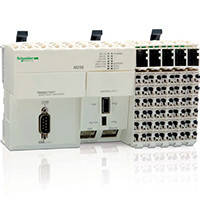
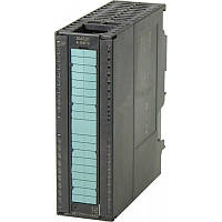
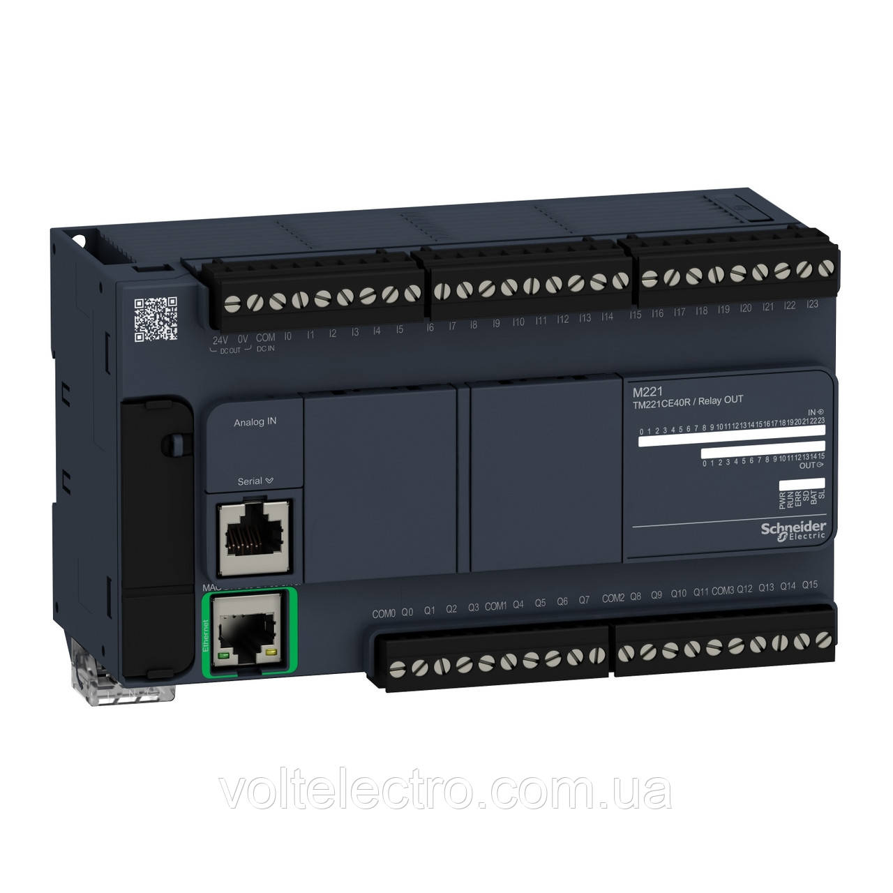
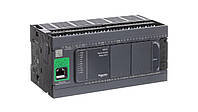
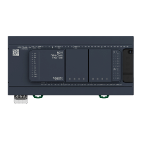
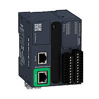
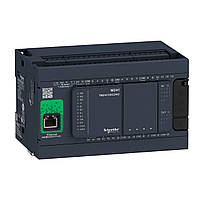
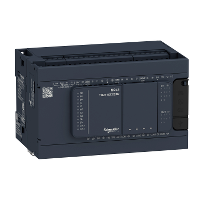
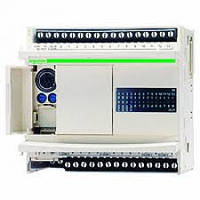
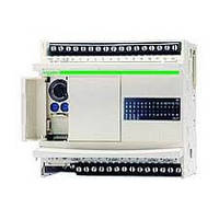
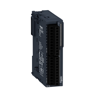
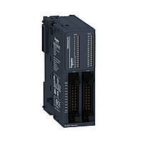
(TM221CE40R) Компактный базовый блок M221-40IO реле Ethernet, Schneider Electric
Код: TM221CE40RНоминальное напряжение питания 100...240 В пер. Ток;
Количество дискретных входов — 24;
Количество дискретных выходов — 16 релейных
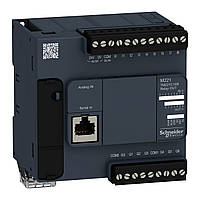
Номер аналогового входа-2 в диапазоне входа:0...10 V;
Напряжение дискретного выхода-5...125 В пост. Ток/5...250 В пер. Ток;
Ток дискретного выхода-2 А;
Кол-во дискретных входов/выходов — 40;
Dimensions Drawings
Dimensions
Mounting and Clearance
Mounting on a Rail

Direct Mounting on a Panel Surface
(1)
Install a mounting strip
Mounting Hole Layout
Mounting
Correct Mounting Position

Acceptable Mounting Position

Incorrect Mounting Position
Clearance
Connections and Schema
Digital Inputs
Wiring Diagram (Positive Logic)

(*)
Type T fuse
Wiring Diagram (Negative Logic)

(*)
Type T fuse
Connection of the Fast Inputs

I0, I1, I6, I7
Relay Outputs
Negative Logic (Sink)
(*)
Type T fuse
(1)
The COM0, COM1, COM2 and COM3 terminals are not connected internally.
(2)
To improve the life time of the contacts, and to protect from potential inductive load damage, you must connect a free wheeling diode in parallel to each inductive DC load or an RC snubber in parallel of each inductive AC load
B
Sink wiring (negative logic)
Positive Logic (Source)
(*)
Type T fuse
(1)
The COM0, COM1, COM2 and COM3 terminals are not connected internally.
(2)
To improve the life time of the contacts, and to protect from potential inductive load damage, you must connect a free wheeling diode in parallel to each inductive DC load or an RC snubber in parallel of each inductive AC load
A
Source wiring (positive logic)
Analog Inputs
The (-) poles are connected internally.
|
Pin |
Wire Color |
|---|---|
|
0 V |
Black |
|
AN1 |
Red |
|
0 V |
Black |
|
AN0 |
Red |
Ethernet Connection

|
Pin N° |
Signal |
|---|---|
|
1 |
TD+ |
|
2 |
TD- |
|
3 |
RD+ |
|
4 |
- |
|
5 |
- |
|
6 |
RD- |
|
7 |
- |
|
8 |
- |
USB Mini-B Connection

SL1 Connection

SL1
|
N ° |
RS 232 |
RS 485 |
|---|---|---|
|
1 |
RxD |
N.C. |
|
2 |
TxD |
N.C. |
|
3 |
RTS |
N.C. |
|
4 |
N.C. |
D1 |
|
5 |
N.C. |
D0 |
|
6 |
CTS |
N.C. |
|
7 |
N.C*. |
5 Vdc |
|
8 |
Common |
Common |
N.C.: not connected
* : 5 Vdc delivered by the controller. Do not connect.
Был online: Сегодня

98% положительных отзывов
12 лет на Prom.ua
500+ заказов
Отзывы о продавце
- Покупатель18.05.2024Актуальное описаниеБыстро отправилиАктуальная ценаТовар был в наличии
- Покупатель17.05.2024Хорошее обслуживаниеАктуальное описаниеБыстро связалисьБыстро отправилиВежливый продавецАктуальная ценаТовар был в наличии
- Покупатель16.05.2024Хорошее обслуживаниеБыстро отправилиАктуальная ценаТовар был в наличии
- Покупатель15.05.2024На даний товар при покупці ціна була в 2 рази менша ніж в конкурентівХорошее обслуживаниеАктуальное описаниеБыстро связалисьБыстро отправилиВежливый продавецАктуальная ценаТовар был в наличии
- Покупатель14.05.2024ШвидкоХорошее обслуживаниеАктуальное описаниеБыстро связалисьТовар был в наличии
- Покупатель12.05.2024Мега швидко відправлено 😃😃Хорошее обслуживаниеАктуальное описаниеБыстро отправилиАктуальная ценаТовар был в наличии
- Покупатель09.05.2024У этого отзыва есть только звездочки, но от этого он не менее хорош.
- Покупатель04.05.2024Хорошее обслуживаниеАктуальное описаниеБыстро связалисьБыстро отправилиВежливый продавецАктуальная ценаТовар был в наличии
- Покупатель04.05.2024Дякую за пораду, оперативність та бажаю Вам вдячних і задоволених покупців!Хорошее обслуживаниеАктуальное описаниеБыстро отправилиВежливый продавецАктуальная ценаТовар был в наличии
- Покупатель01.05.2024Быстро отправилиВежливый продавецАктуальная ценаТовар был в наличии

Похожее у продавца


Покупают вместе у этого продавца


Логический контроллер M221 40 входов/выходов, реле, Ethernet
Код: TM221CE40RВ наличии
19 060 ₴
21 178 ₴
Заказ этого товара — от 1 шт.
- Оплачивай безопасно картой

Доставка
 Нова ПоштаУзнать дату доставки в
Оплата и гарантии
 Безопасная оплата картойБез переплат
Prom гарантирует безопасность
Вернем деньги при отказе от посылки Наложенный платежНова Пошта, Самовывоз, Укрпошта
Похожее у других продавцов